Enhance Wind Turbine Design with the New Wolfram System Modeler Rotating Machinery Library

Explore the contents of this article with a free Wolfram System Modeler trial. A wind turbine gearbox, susceptible to erratic wind loads, frequently fails well before its intended lifespan. Such failures, occurring globally, not only cause significant downtime but also lead to substantial economic losses. Can simulations help avoid this?

In addition to many other exciting updates to Wolfram System Modeler, we just released the Rotating Machinery library. This library is a powerful tool to simulate an array of critical rotating machinery components, such as bearings, gears, flexible shafts and discs, with high precision. These can be modeled both individually and as part of a larger system capturing dynamic behavior with high fidelity.
In this blog, I will delve into the intricacies of wind turbine design challenges and solutions using the Rotating Machinery library. I will also focus the analysis on maintaining gear contact pressures and foundation forces within design thresholds.
In the first part of our experiment, I will show how to model and simulate the gearbox specifics of the widely used ACCIONA wind turbine, specifically the AW-100/3000 model. Using this, I will verify that the gearbox is within allowable stress limits.
In the second part, I’ll incorporate the mast, shafts and blades into the model to check if the gearbox continues to meet the design criteria. Adding these components will enhance the model’s accuracy, allowing it to better reflect the actual dynamics at play.
Part 1: Modeling the Gearbox of a Wind Turbine
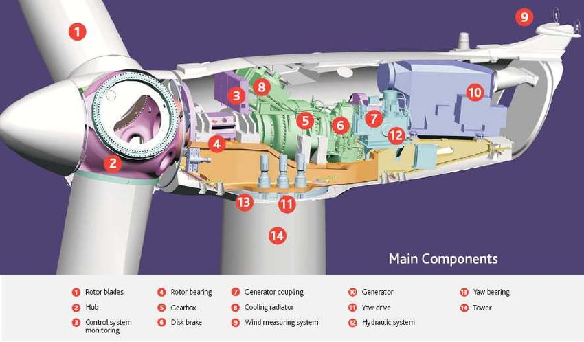
Let’s begin with an in-depth model of the ACCIONA AW-100/3000 gearbox. The gearbox has two parts: a planetary gear and a three-stage gearbox. We can see the gearbox marked in the following image:

ACCIONA AW-x/3000 nacelle layout (image: ACCIONA)
Using ready-made components from the library, I model the gearbox system, including a planetary gear, a three-stage gearbox, a shaft in between and a corresponding support, as shown in the following. All the specifics of the respective gearbox are defined by parametrizing things like wheel geometries, number of teeth and profile shifting. Now we are ready to simulate and analyze:

In the simulation, I apply a speed profile starting at a standstill and accelerating to the operating speed of 20 rpm, as shown by the blue line in the following figure. We can also see the rotational speed of the sun wheel (i.e. the center wheel) in green and one of the planet wheels in orange:

Other than the expected difference in speeds due to gear ratios, we also see that the planet wheel seems to vibrate a lot compared to the others. This could be caused by backlash between the different wheels; this might be reduced by changing a variable such as the profile shift (i.e. the teeth geometries and gap), but for now, we will focus on analyzing the contact stresses instead.
Let’s start by taking a look at a visualization of the planetary gear and three-stage gearbox. The images are screenshots from the animation in System Modeler. On the left, we see the planetary gear, and on the right the three-stage gearbox. In both cases, I have marked the contact points that I will be studying. I selected these because they had the largest contact pressure when looking at the simulation results:

In the following, I plot the stress acting on the selected tooth contact pairs with the allowable stress limit for AISI 5160 steel, which is one of the steels used in the ACCIONA turbine, 1800 MPa. Notice that the peak contact stresses are greater in the planetary gear but remain below the maximum allowable limit:

But perhaps there is more to the story than this. The following figure shows the contact pressure at the two locations during the same time interval. Observe that the planetary gear (top figure) rotates slower, and, therefore, each contact takes more time. More interestingly, we can also see that there are a lot of vibrations, especially on the planetary gear. Vibrations are often a cause of failure, so this is something that should be investigated further to understand the potential consequences. This investigation would require its own dedicated blog, so I will not include this here. If you are interested in understanding how to do this kind of frequency analysis, you can read this post:

Part 2: The Complete Large-Scale Wind Turbine Model
Building on our understanding of gearbox dynamics, let’s move toward a more complete model. This model also includes a flexible rotor with blades, a tower and an additional bearing:

The following image shows a snapshot of the animation that illustrates the combination of the gearbox with a planetary gear and a three-shaft gearbox, providing a more comprehensive understanding of the system. The ACCIONA AW-100/3000 wind turbine model has a 100-meter hub height, which can be modeled by the flexible beam component from the Rotating Machinery library:

In the following animation, we can observe the rotation of each wheel gearbox. It is easy to see that there is a big difference in speed between the blades and the outgoing shaft. In fact, the propeller rotates at 20 rpm, while the outgoing shaft is doing 1560 rpm, corresponding to a total gear ratio of 77.8. The high speed is tuned to maximize the performance of the generator it drives:
In the following plot, we show the rotational velocities of the different components of the planetary gears, just as we did in the first part of the blog. You can observe that there are more vibrations now. These are caused by the dynamics related to the blades, tower and shafts:

The big question is whether these higher vibrations lead to problems with the allowable limit for contact stress. In the following plot, we can see a comparison of the contact pressures from the gearbox-only model (in orange) and the full system model (blue). It is easy to see with the naked eye that we are now much closer to the allowable limit of 1700 MPa. However, the simulations show that we are still within it:

While in this case we still ended up within the limit, the analysis highlights the necessity of paying attention to small details while considering the entire system. This is exactly where the Rotating Machinery library and System Modeler excel.
For more information on modeling wind turbines, check out the Wolfram System Modeler libraries and interact with examples like “High-Fidelity Wind Turbine Mast.”
|
Don’t miss Wolfram U’s course “Testing and Modeling Turbines, Gears and Drivelines with the Rotating Machinery Library” on Wednesday, March 20. |


Comments